FAQ about Controller
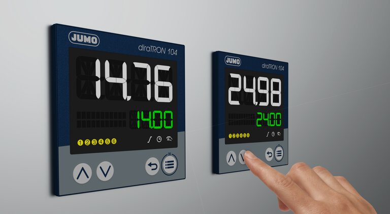
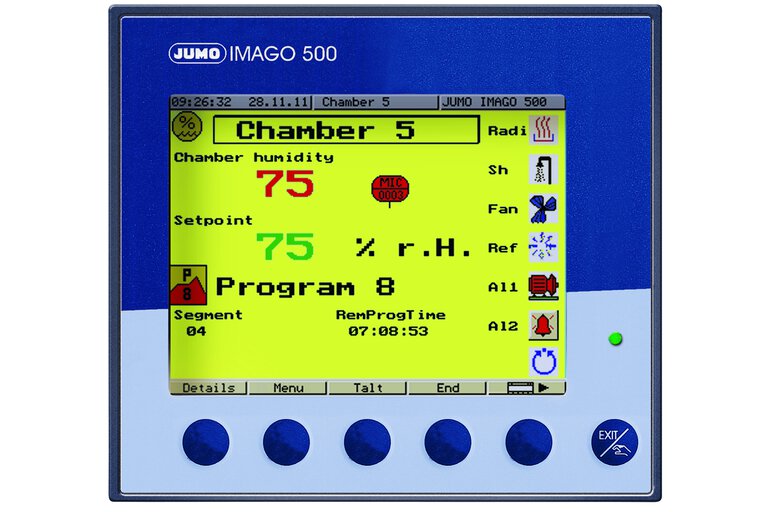
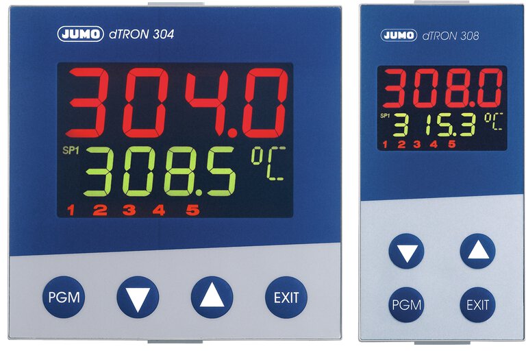
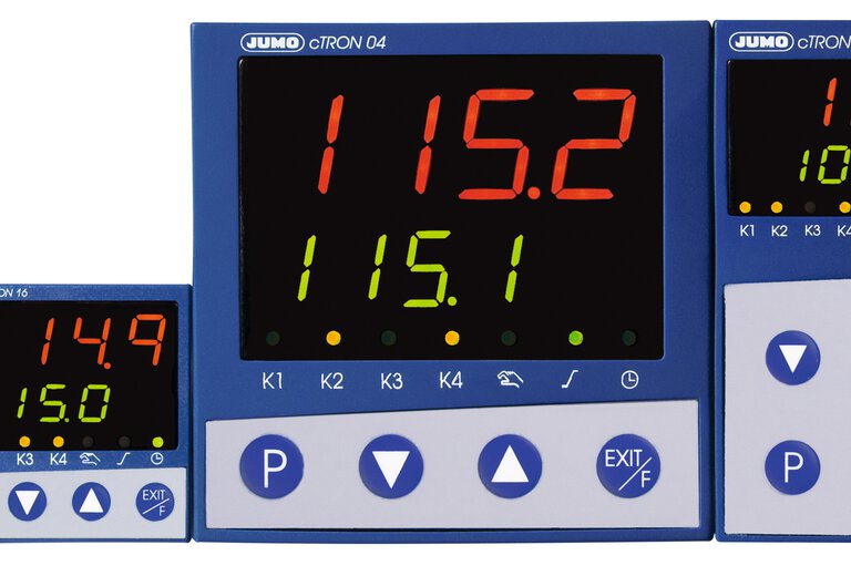
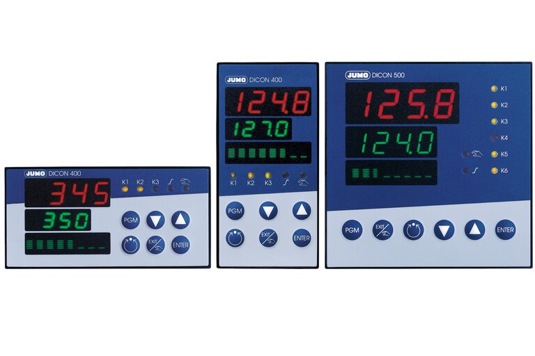
All FAQs for Basics, Startup and the products Compact controller JUMO dTRON 16.1, Compact controller JUMO cTRON, Multi-channel proceses and program controller JUMO IMAGO 500, Process controller JUMO DICON 400, 500, 501 and Compact controller JUMO dTRON 304/308/316
Startup
Auxiliary material - Controller optimisation
System optimization made easy - Controller startup software from JUMO
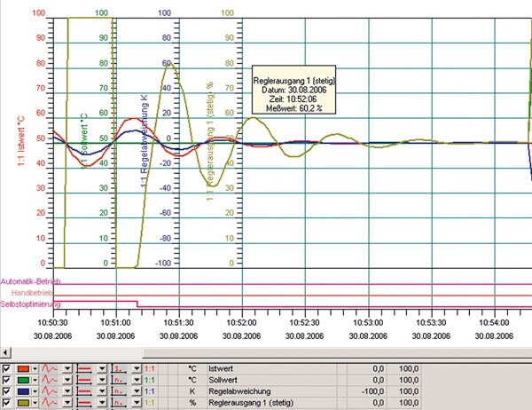
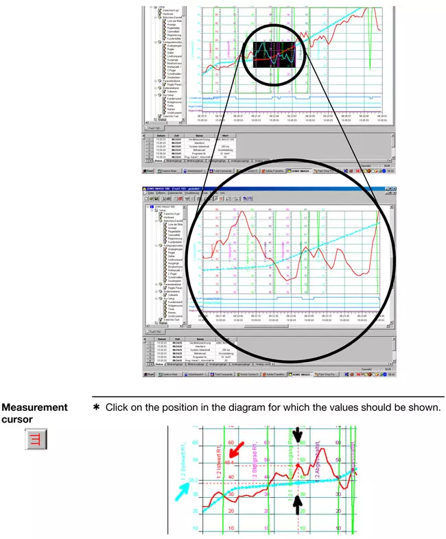
Controllers such as the JUMO IMAGO 500, JUMO DICON 500, and now the new JUMO dTRON series, include a special software tool in the setup program, for monitoring and documenting the commissioning, thus making it considerably easier.
This startup software enables the visualization and storage of analog and binary signals while the system is being optimized.
Especially for complex processes, a real-time visual presentation of the most important process data is practically indispensable for the control engineer.
All you need for system optimization is one of the controllers mentioned above, a PC or laptop with the setup program, and an interface connection through a setup cable with an RS232 or USB interface. This connection is required anyway for the setup programming, and is therefore usually available.
Important settings, such as the free selection of signals to display the individual analog and binary values in the instrument, zoom, various print options, showing or hiding individual curves, free scaling and choice of colors are all included in this software tool as standard.
The principal functions of the program cover:
- monitoring and documentation of the tuning or auto-tuning phase
- generation of a setpoint step change to determine and record the control-loop characteristics on the basis of the loop response
- comparison of several different control loop results using varied control parameters
- a sampled check of the control loop quality during production operation or when a tool is changed
- saving these data files for quick dispatch by e-mail to an expert advisory team.
The program is not just useful, it also provides a lot of other advantages – also economic advantages – over conventional process control monitoring, such as:
- no additional recorders or other peripherals required for commissioning
- very little time required for assembly and cabling of the measurement setup
- no attaching of extra sensing equipment to the system or the analog signals from the controller
- considerable time-saving through the simple Plug & Play interface cable
- all the important process data at a glance
- simultaneous documentation of the system and/or commissioning data.
Startup program - Operation advice - Example: JUMO IMAGO 500
Basics
General note on optimization
Controller optimization (or tuning) is the adjustment of the controller to a given process or control loop. The control parameters have to be selected such that the most favorable response of the control loop is achieved under the given operating conditions. However, this optimum response can be defined in different ways, such as reaching the setpoint quickly, with a small overshoot, or a somewhat longer stabilization time with no overshoot. If all that is expected of the controller is a response such as for a limit contact (without pulsed operation), there is no need to find the optimum settings for proportional band, derivative time or reset time. Only the switching differential has to be predefined.
In most cases, the controller can itself determine the control parameters through the self-optimization (autotuning) facility, if the process permits self-optimization. Alternatively, the optimum parameter setting can be determined "manually", through experiments and empirical equations (see formulae in the appendix).
When controllers are swapped, or with identical control installations, control parameters can also be directly accepted or entered.
After a manual parameter setting, autotuning may no longer be started, since this would overwrite the settings.
Formulas for setting according to the oscillation method:
| Controller action |
|
| P | XP = XPk / 0,5 |
| PI | XP = XPk / 0,45 T P = 0,85 ·TK |
| PID | XP = XPk / 0,6 Tn = 0,5 · TK Tv = 0,12 · TK |
Formulas for setting according to the step response:
| Controller action | Control loop | Error |
| P | XP = 3,3 · KS · (Tu/Tg) · 100 % | XP = 3,3 · KS · (Tu/Tg) · 100 % |
| PI | XP = 2,86 · KS · (Tu/Tg) · 100 % T n = 1,2 · Tg |
XP = 1,66 · KS · (Tu/Tg) · 100 % T n = 4 · Tu |
| PID | XP = 1,66 · KS · (Tu/Tg) · 100 % T n = 1 · Tg T v = 0,5 · Tu |
XP = 1,05 · KS · (Tu/Tg) · 100 % T n = 2,4 · Tu T v = 0,42 · Tu |
Controller characteristic/operating sense (definitions/selection criteria)
inverse: The controller output Y is larger than 0, or the relay
is energized, when the process value is smaller than the setpoint (e.
g. heating).
direct: The controller output Y is larger than 0, or the relay
is energized, when the process value is larger than the setpoint (e. g.
cooling).
Why is a 3-state controller unsuitable for actuator drives?
The modulating controller, like the 3-state controller, has two switching control outputs, which are, however, designed especially for motorized actuator drives, e.g. for opening or closing. If a continuous output signal is required for the 3-state controller in order to maintain a certain output level, we can see that, in the case of the modulating controller, the electrical actuator drive will remain in the position reached when there is no further signal from the controller.
Accordingly, the actuator drive can remain 60 % open, for example, although it is not operated by the controller at this instant.
What is meant by digital input filter (dF)?
The digital input filter (dF) serves to dampen the input signals and affects both indication and controller. The larger the value for "dF", the larger the damping of the input signal. An extremely high or low value can have a negative influence on the control quality. In most cases, the default setting for "dF" can be used for operation.
What is meant by 3-state controller?
3-state controllers have two outputs which may be either switching or
continuous (relay contact or e.g. 4 - 20 mA). 3-state controllers are
used if the control variable has to be or can be influenced through two
actuators with opposing action.
This may be a climatic cabinet with
a thyristor power unit for the electric heating and a solenoid valve
for cooling. In this example, a 3-state controller with a continuous
(analog) output for the heating function (controller output 1) and a
switching output for the cooling function (controller output 2) would be
the best choice.
On 3-state controllers, the parameters
proportional band, reset time, derivative time and hysteresis, familiar
from 2-state controllers, can often be set separately for both operating
senses. The 3-state controller additionally features the parameter
What is meant by modulating controller?
Modulating controllers have two switching outputs and are especially
designed for operating actuator drives which can, for instance, open or
close a flap valve.
Actuators/actuator drives that can be operated:
AC motor actuators, DC motors, 3-phase motor actuators, hydraulic cylinders with solenoid valves etc.
What is meant by cascade control?
Cascade control can significantly improve the control quality. This applies in particular to the dynamic action of the control loop, in other words, the transition of the process variable following setpoint changes or disturbances.
Example 1: schematic construction of a cascade
Chocolate has to be heated to vs = 40 °C for processing. The chocolate temperature must nowhere exceed 50 °C (even close to the heater). It is therefore heated on a water bath.
Cascade control is used in order to achieve rapid stabilisation.
Controller 1 is always the master controller, controller 2 always the slave.
The setpoint for the slave controller is produced by output conversion.
The control output y1 is converted to a setpoint using the unit of the process value x2 (here: 0 - 100 % = 0 - 50 °C).
List of symbols
O2 - Output 2
I1 - Analogue input 1
I2 - Analogue input 2
C1 - Controller 1
C2 - Controller 2
w
1 - Setpoint controller 1
w
2 - Setpoint controller 2
x
1 - Process value controller 1
x
2 - Process value controller 2
x
w1 - Deviation controller 1
x
w2 - Deviation controller 2
y
1 - Control output 1
y
2 - Control output 2; output 1 of controller 2
v
s - Chocolate temperature
v
w - Water bath temperature
Example 2: construction of a trimming cascade
Two charges of chocolate have to be heated to 40 °C and 50 °C. The chocolate temperature must nowhere (not even close to a heater) exceed the setpoint by more than 10 °C. It is therefore heated on a water bath.
Trim cascade control is used to achieve rapid stabilisation without overshoot and without altering the controller configuration (output conversion) at a change of setpoint (batch change).
Controller 1 is always the master controller, controller 2 always the slave controller.
The setpoint for the slave controller is produced by output conversion and the addition of the master controller setpoint (w1).
In setpoint conversion, the control output y1 is converted to a value with the unit of the process value w2. It corresponds to the maximum permitted temperature difference (± | x1 - w1 |; here: 0 - 100 % = -10 to +10 °C).
List of symbols
O2 - Output 2
I1 - Analogue input 1
I2 - Analogue input 2
C1 - Controller 1
C2 - Controller 2
w1 - Setpoint controller 1
x1 - Process value controller 1
x2 - Process value controller 2
xw1 - Deviation controller 1
xw2 - Deviation controller 2
y1 - Control output 1
y2 - Control output 2; output 1 o controller 2
vs - Chocolate temperature
vw - Water bath temperature
What is meant by contact spacing?
If the process variable varies within a fixed interval about the
setpoint - the contact spacing Xsh - then neither of the outputs is
active. Exception: 3-state controllers with I and D components. Within
the contact spacing, only the proportional component is inactive.
This contact spacing is necessary to prevent continual switching
between the two manipulating variables, e.g. heating and cooling
registers, when the control variable is unsteady. The contact spacing
is also commonly called the dead band. Too small a dead band can lead
to a pointless waste of energy in a plant.
What is meant by reset time?
The I component of the controller output signal has the effect of continuously altering the manipulating variable, until the process value has reached the setpoint.
As long as the control deviation is present, the manipulating variable is integrated upwards or downwards. The longer the control deviation continues to be present in a controller, the larger the integral effect on the manipulating variable. The larger the control deviation and the smaller the reset time, the more pronounced (faster) the effect of the I component.
The I component ensures stabilization of the control loop without permanent control deviation. The reset time is a measure of the effect the control deviation duration has on the control action. A larger reset time means that the I component is less effective and vice versa. Within the specified time Tn (in sec.), the change in the manipulating variable that is produced by the P component (xp or pb), is added once more. Accordingly, there is a fixed relationship between the P and the I component. A change in the P component (xp) also means a changed time response, at a constant value for Tn.
What is meant by proportional band (Xp1, Xp2)?
In a purely proportional controller (P controller) the manipulating variable (controller output Y) is proportional to the control deviation within the proportional band (Xp). The gain of the controller can be matched to the process by altering the proportional band. If a narrow proportional band is chosen, a small deviation is sufficient to achieve a 100 % output, i.e. the gain increases as the proportional band (Xp) is reduced. The reaction of the controller to a narrow proportional band is faster and more pronounced. A proportional band that is too narrow will cause the control loop to oscillate. Any alteration of the proportional band will also affect the I and D action of a PID controller to the same extent.
If the proportional band is set to zero, the controller action
is ineffective. This means that the controller operates solely as a
limit contact. The selected hysteresis or switching differential is
effective, the settings for the derivative time and the reset time,
however, are not taken into account.
For all controller types, except for the 3-state (double-setpoint)
controller, only the proportional band Xp1 is relevant. With 3-state
controllers only, separate settings for the proportional band (for both
operating senses) are necessary (e. g. Xp1 for heating and Xp2 for
cooling).
What is meant by switching differential/hysteresis?
The switching differential is also referred to as hysteresis and is only relevant for switching controllers with proportional band = 0.
For controllers with inverse operating sense (e.g. heating control), the standard response is as follows:
The switching differential lies below the setpoint. This means that the controller switches off precisely then when the setpoint is exceeded. It only switches on again when the process value has fallen below the switch-on point, which lies below the setpoint by the amount of the switching differential.
On controllers with direct operating sense (e. g. cooling), the switching differential normally lies above the setpoint. As for controllers with inverse operating sense, the switch-off point is precisely at the setpoint. However, it is switched on again above the setpoint, shifted by the amount of the switching differential.
Switching action of a 2-state controller with inverse operating sense:
Switching action of a discontinuous 3-state controller:
What is meant by actuator stroke time (tt)?
The actuator stroke time is a variable provided by the actuator drive
and is therefore only relevant for modulating controllers or
proportional (continuous) controllers with integral actuator driver.
The time that the actuator drive takes to travel once across the full
usable manipulation range is set under actuator stroke time.
The actuator stroke time cannot be determined by self-optimization (autotuning). It must always be set before the optimization.
The actuator stroke time provides the controller with information about
the effect of the actuating pulses. At an actuator stroke time of 20
seconds, for example, the percentage change in manipulating variable, at
the same actuating pulse, is significantly larger than for an actuator
with 100 seconds stroke time, for example.
When selecting or dimensioning actuator drives, it must be taken into
account that a short stroke time of, say, less than 10 seconds will
result in large steps of the manipulating variable, and consequently to a
reduced control accuracy. If, for example, we assume that 0.5 seconds
is the shortest actuating pulse time, a stroke time of 10 seconds would
result in only 20 actuating steps. This would mean that the manipulating
variable can only be changed in 5 % steps.
Actuator drives with a very long stroke time can, however, be
disadvantageous as far as the dynamics is concerned, because the
manipulating variable can only be changed relatively slowly by the
control action. In actual operation, however, problems arising from
stroke times that are too short occur more frequently than those caused
by stroke times that are too long.
What is meant by proportional controller with integral actuator driver?
The short form "actuating controller" is used to describe a "proportional controller with integral actuator driver". In contrast to the modulating controller, an actuator feedback signal is essential for the actuating controller.
The actuating controller controls the clockwise or anticlockwise movement of the motorized actuator via 2 switching outputs.
The position of the motorized actuator is registered and compared with the manipulating variable (yR) of the proportional controller.
What is meant by derivative time?
The intensity of the D component (differential component) can be set via the derivative time. The D component of a controller with PID or PD action reacts to the rate of change of the process value.
When the setpoint is approached, the D component acts as a brake, thereby preventing the control variable from overshooting the setpoint.
Basically, the D component has the following effects:
As soon as the control variable changes, the D component reacts against this change.
For a controller with an inverse operating sense (i.e. for heating) this would mean, for example
- if the control variable decreases as a result of a disturbance in the process, the D component forms a positive manipulating variable, which counteracts the reduction in control variable.
- if the control variable increases as a result of a disturbance in the process, the D component forms a negative manipulating variable, which counteracts the increase in control variable.
- The damping action increases with the size of the setting for the derivative time (value in seconds).
What is meant by 2-state controller?
The 2-state controller (ON/OFF controller) switches the output when the
setpoint is reached. If the value falls below the setpoint by a
certain adjustable tolerance (xsd, switching differential, hysteresis),
then the output is switched on again. It therefore only has two
switching states. It is used in temperature control applications where
the heating or cooling is only switched on or off.
A 2-state controller with dynamics can, however, also operate with a P, I, or D component.
What is meant by cycle time (Cy)?
The switching cycle time is quoted in seconds and defines the period during which a full switching cycle consisting of switch-on and switch-off times takes place.
Generally, the cycle time should be selected so that the actual control process can still be smoothed out. At the same time, the switching frequency must always be taken into account.
The response can best be reset in manual mode so that the direct influence of the manipulating variable on the cycle time can be monitored. With a manipulating variable of 50 %, "Ton" and "Toff" are equal. If the manipulating variable is altered, this ratio alters accordingly.
